Document Actions
HYLOW
Theory of the HPW
The Hydrostatic Pressure Wheel (HPW) consists of a large diameter wheel of radius R with vertical blades, which are deeper than the upstream water depth d1, and which are located above a drop in water level elevation e.g. at a weir, Fig. 1. A downstream water depth d2 < d1 is assumed to be kept constant by another weir further downstream. The wheel blades maintain the head difference d1 – d2; for this purpose the river bed is slightly curved to minimize losses (for simplicity not shown in the figure).
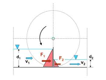 |  |
| Fig. 1: HPW principle and theory |
The hydrostatic pressure acts on the blade from up- and downstream; the resulting force on the blade travels with the velocity v1 of the flow (and blade) and generates power. Losses are neglected. For simplicity, the radius of the wheel of unit width shown in Fig. 1 is assumed to be infinite.
Available hydraulic power Phyd:
![]() (1)
(1)
Hydrostatic force on the blade F:
![]() (2)
(2)
Since the radius of the wheel is infinite, the blades always remain vertical, and the force F moves with the same velocity v1 as the blade. The power P at the blade becomes:
![]() (3)
(3)
This gives an efficiency η without losses
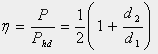 for
for  (4)
(4)
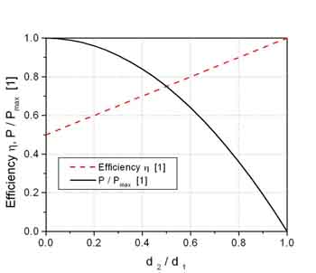
Fig. 2 shows the efficiency and the normalised power, i.e. P / P (d2 / d1 = 0) for constant flow volume as a function of d2 / d1. The efficiency becomes a linear function of the depth ratio d2 / d1 , and ranges from 0.5 for d2 / d1 = 1 to 1 for d2 / d1 = 0, whilst the power reduces continuously from maximum to zero.
Experiments
A series of tests was conducted with a wheel of 0.80 m diameter in a 300 mm high, 300 mm wide and 20 m long tank at the Technical University of Darmstadt. In the tests described here, the downstream water level was regulated with a weir at the end of the flume; the flow volume was kept constant at 15 l/s. The wheel had 12 blades, with a gap width between tank walls / bottom and blades of 2 mm. At the bottom of the tank, a curved section which covered one cell (the space between two blades) was provided to minimize losses. Fig. 3 shows the experimental and theoretical efficiencies as a function of d1 / d2. It can be seen that experimental efficiencies are 5 – 10% below the theoretical values; this can be mainly attributed to gap losses measured at 0.8 to 1.2 l/s.
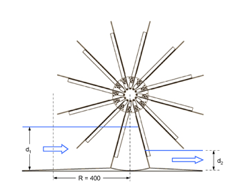 | 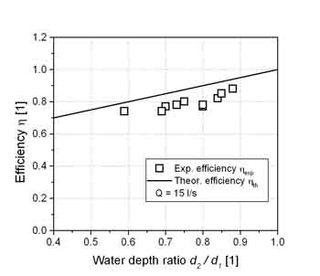 |
| Fig. 2: Experiment and results |
Smaller values than 0.54 for t2 / t1 were very difficult to achieve since the flow velocities downstream became very large. Upstream water depths were in the range of 0.14 to 0.23 m, with the corresponding values for d2.
During the experiments, it was found that equal ratios of d2 / d1 could be achieved for different values of d1 and d2 and constant flow volume Q, whereby the lower water depths resulted in higher wheel speeds, and lower efficiencies. The question therefore arose whether the operational condition which establishes itself is a function of the prescribed parameters t2 (through the downstream weir) and Q (through the water supply) or not.
References
Müller G. and Senior J., 2007, Die Wasserdruckmaschine mit freier Oberfläche – ein neuer Energiewandler für sehr niedrige Fallhöhen, Zehntes Internationales Anwenderforum Kleinwasserkraftwerke, Ostbayerisches technologie-Transfer Institut (OTTI) e.V., Regensburg, 26-31.
Troger M., 2008, Wie effizient sind Wasserräder zur Gewinnung von Energie in Fließgewässern mit geringen Fallhöhen? (How efficient are water wheels for energy generation in rivers with very low head differences?, in German), Diplomarbeit, Institut für Wasserbau und Wasserwirtschaft, Technische Universität Darmstadt
FP7-Energy-2007-1-RTD project number: 212423